QMKでArduino用キーボードを作る (1/4 テスター編)
キーボード #2 Advent Calendar 2020
に参加しています。
3日目 Arduino
やりたいこと
Arduino用のキーボードを作ってみる。
正しくは、Arduino で利用できるキーボードをQMKで作る。
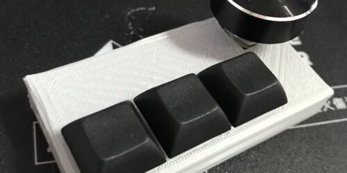
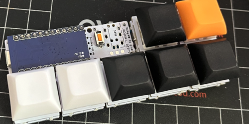
USB(HID)のキーボードは、 su120キットのおかげで作れるようになったので、それを改造する。
special thanks to @e3w2q さん
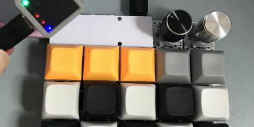
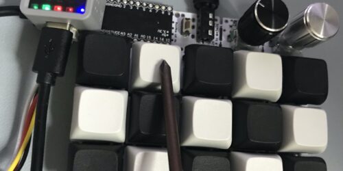
完成図
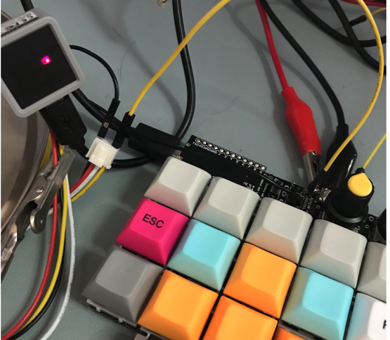
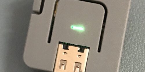
Arduino 側は、ATOM Matrix で作成。今後もテスターとして利用できるようにする。
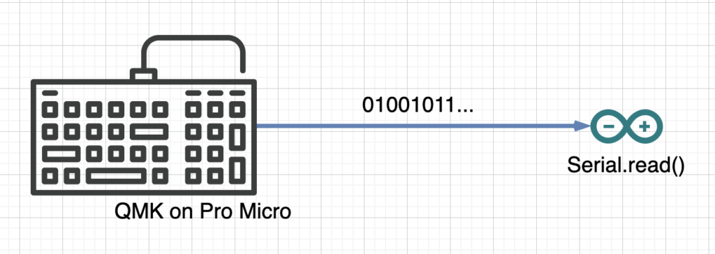
通信はをシリアル接続(8N1)で、ATOM Matrixには押されたキーの位置をLEDで表示する。
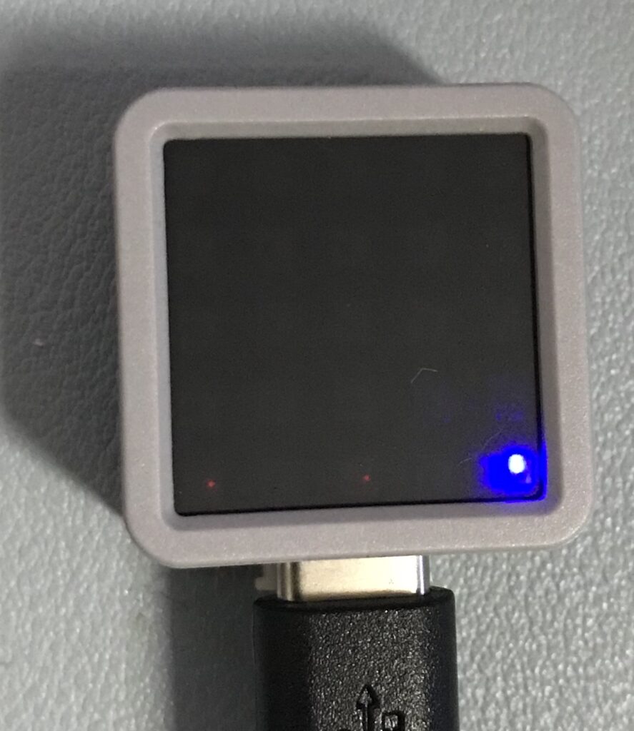
ATOM Matrix は、ESP32 Pico に 5x5 のフルカラーLEDを実装したかわいいやつ。
I/F仕様
シリアル通信の仕様(Network層)
- 電圧 5V
- bitrate ... QMXの最低である20Kbps
- bit数 ... 8bits
- parity ... なし
- stop bit ... 1bit
キーのMatrixデータ仕様 (Transport層)
1回の送信で7bytes。
byte | bits | 値 | 説明 |
---|---|---|---|
1 | 1-5 | 0 or 1 | キーボード1行目の押し込み状態 |
2 | 1-5 | 0 or 1 | キーボード2行目の押し込み状態 |
3 | 1-5 | 0 or 1 | キーボード3行目の押し込み状態 |
4 | 1-5 | 0 or 1 | キーボード4行目の押し込み状態 |
5 | 1-8 | 0-127 | 左側のロータリーエンコーダーの値 |
6 | 1-8 | 0-127 | 右側のロータリーエンコーダーの値 |
7 | 1-8 | 0xff | データの最後EOF |
ex
押したキー | Matrixデータ |
---|---|
なし | 00:00:00:00:00:00:ff |
1行目1列 | 80:00:00:00:00:00:ff |
2行目1列 | 00:80:00:00:00:00:ff |
2行目1列と2列 | 00:c0:00:00:00:00:ff |
2列目全部 | 40:40:40:40:00:00:ff |
3行目のキー5個全部 | 00:00:f8:00:00:00:ff |
ATOM Matrix でテスターを作成
QMK の改造をする前に、正しい動作を確認するためのテスターを作る。
シリアル通信部分
だれでも簡単。Serial のread でデータを読める。
例えば、こんな感じ。
void setup() {
...
// Serial1 の設定
Serial1.begin(20000, SERIAL_8N1, PIN_RX, PIN_TX);
}
void loop() {
if (Serial1.available()) {
int inByte = Serial1.read()
if (inByte == 0xff) {
// stop data
テスターの実装
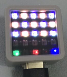
テスター仕様は、ATOM Matrix の5x5のLEDのうち、上位4行でキーボードの押した位置を点灯。
5行目の1,2カラムは、左のエンコーダ値。
5行目の3,4カラムは、右のエンコーダ値。
5行目の5カラムは、serialでデータを受け取ると、点滅する。
This file contains bidirectional Unicode text that may be interpreted or compiled differently than what appears below. To review, open the file in an editor that reveals hidden Unicode characters.
Learn more about bidirectional Unicode characters
#include "M5Atom.h" | |
//#define PIN_RX 22 // G0 | |
#define PIN_RX 32 // GROVE | |
#define PIN_TX 26 | |
#define PIXEL_PER_ROW 5 | |
// Matrix Display Buffer | |
uint8_t DisBuff[2 + 5 * 5 * 3]; | |
#define ORANGE 0xe07020 | |
#define GRAY 0x686868 | |
#define RED 0x701212 | |
#define BLUE 0x000070 | |
#define GREEN 0x00ff00 | |
uint32_t DisColormap[] = { | |
// keyboard color map | |
GRAY, ORANGE, GRAY, ORANGE, GRAY, | |
ORANGE, GRAY, ORANGE, GRAY, ORANGE, | |
GRAY, ORANGE, GRAY, ORANGE, GRAY, | |
GRAY, GRAY, GRAY, GRAY, GRAY | |
}; | |
void setup() { | |
// serial console init | |
Serial.begin(115200); | |
// ATOM Matrix init | |
M5.begin(true, false, true); | |
delay(10); | |
Serial1.begin(20000, SERIAL_8N1, PIN_RX, PIN_TX); // EXT_IO | |
Serial.println("start"); | |
M5.dis.drawpix(24, GRAY); | |
} | |
uint8_t SerialBuff[128]; | |
uint16_t SeirialBuffSize = 0; | |
void draw_matrix() { | |
// keycode | |
// 1 2 3 4 5 : 1byte(1-5) | |
// 6 7 8 9 10 : 1byes(6-8) 2bytes(1-2) | |
// 11 12 13 14 15 : 2byte(3-7) | |
// 17 19 20 : 3byte(1, 3-4) | |
// encoder | |
// LEFT ENCODE VALUE(0-127) : 5byte(1-8) | |
// RIGHT ENCODE VALUE(0-127) : 6byte(1-8) | |
DisBuff[0] = 0x05; | |
DisBuff[1] = 0x05; | |
// keyboard matrix | |
for (int row = 0; row < 4; row++) { | |
uint8_t val = SerialBuff[row]; | |
for (int col = 0; col < PIXEL_PER_ROW; col++) { | |
uint32_t color = 0; | |
uint32_t pixel = row*PIXEL_PER_ROW + col; | |
uint32_t buf_offset = pixel * 3; | |
if (val & 1<<col) { | |
color = DisColormap[pixel]; | |
} | |
uint8_t red = (color &0xff0000)>>16; | |
uint8_t green = (color &0xff00)>>8; | |
uint8_t blue = (color &0xff); | |
DisBuff[2 + buf_offset + 0] = red; | |
DisBuff[2 + buf_offset + 1] = green; | |
DisBuff[2 + buf_offset + 2] = blue; | |
// M5.dis.drawpix(row*5+col, 0x707070); | |
} | |
} | |
// encoder | |
for (uint8_t encoder_hand = 0; encoder_hand < 2; encoder_hand++) { | |
uint8_t pixel_row = 4; | |
uint8_t data_offset = 4/*enconder byte*/ + encoder_hand; | |
uint8_t encoder_val = SerialBuff[data_offset]; | |
uint8_t color[2]; | |
color[0] = ((encoder_val & 0x0f)<<1) | 0x01; // val < 128 | |
color[1] = (((encoder_val & 0xf0)>>4)<<1) | 0x01; // val >= 128 | |
for (uint8_t col = 0; col < 2; col++) { | |
uint32_t pixel = pixel_row*PIXEL_PER_ROW + encoder_hand * 2 + col; | |
uint32_t buf_offset = pixel * 3; | |
uint8_t red = 0; | |
uint8_t green = 0; | |
uint8_t blue = 0; | |
if (encoder_hand == 0) { | |
// left hand | |
green = color[col]<<3; | |
} else { | |
// right hand | |
red = color[col]<<3; | |
} | |
DisBuff[2 + buf_offset + 0] = red; | |
DisBuff[2 + buf_offset + 1] = green; | |
DisBuff[2 + buf_offset + 2] = blue; | |
// DisBuff[2 + buf_offset + 0] = 0x70; | |
} | |
} | |
M5.dis.displaybuff(DisBuff); | |
} | |
void loop() { | |
if (Serial1.available()) { | |
int inByte = Serial1.read(); | |
M5.dis.drawpix(24, 0x000070); | |
if (inByte == 0xff) { | |
// stop data | |
for (int i =0; i < SeirialBuffSize; i++) { | |
Serial.printf("%02x", SerialBuff[i]); | |
} | |
Serial.println(""); | |
draw_matrix(); | |
SeirialBuffSize = 0; | |
} else { | |
// matrics data | |
SerialBuff[SeirialBuffSize] = inByte; | |
if (SeirialBuffSize++ >= sizeof(SerialBuff)) { | |
Serial.println("error"); | |
SeirialBuffSize = 0; | |
} | |
} | |
} else { | |
delay(50); | |
} | |
M5.update(); | |
} |
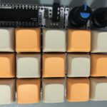
全部のキーを押すとこんな表示になる。