QMKでArduino用キーボードを作る (1/4 テスター編)
目次
キーボード #2 Advent Calendar 2020 に参加しています。
3日目 Arduino

やりたいこと
Arduino用のキーボードを作ってみる。
正しくは、Arduino で利用できるキーボードをQMKで作る。
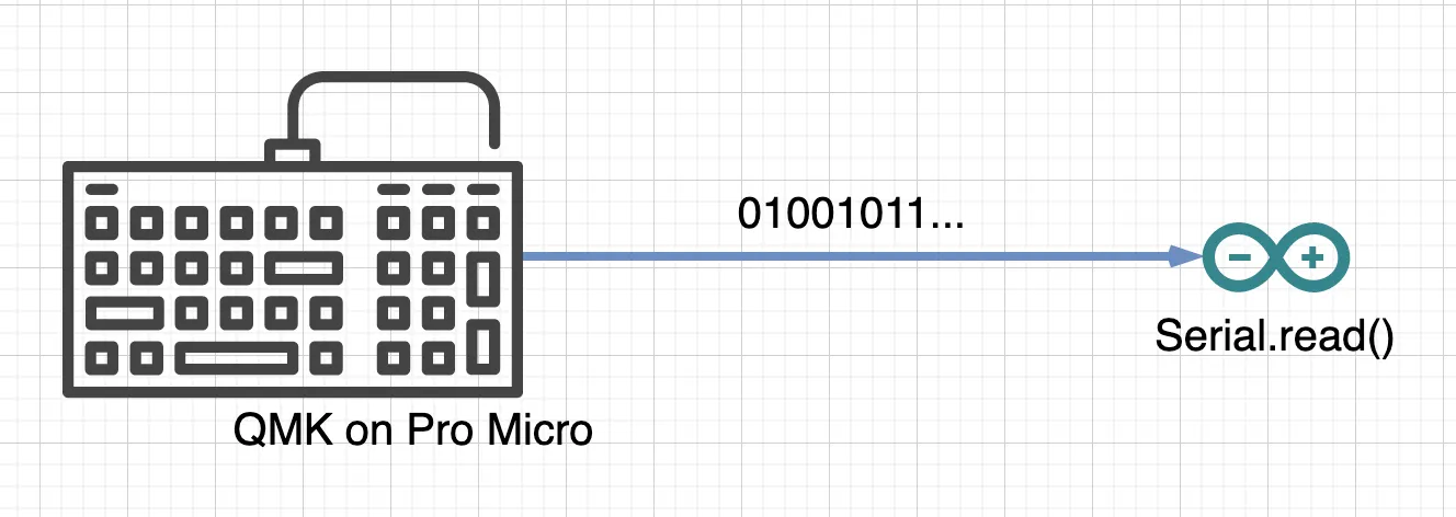
USB(HID)のキーボードは、 su120キットのおかげで作れるようになったので、それを改造する。
special thanks to @e3w2q さん
完成図
Arduino 側は、ATOM Matrix で作成。今後もテスターとして利用できるようにする。
通信はをシリアル接続(8N1)で、ATOM Matrixには押されたキーの位置をLEDで表示する。
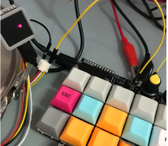
ATOM Matrix は、ESP32 Pico に 5x5 のフルカラーLEDを実装したかわいいやつ。
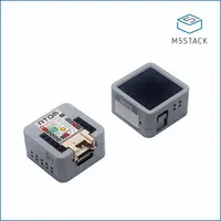
I/F仕様
シリアル通信の仕様(Network層)
- 電圧 5V
- bitrate ... QMXの最低である20Kbps
- bit数 ... 8bits
- parity ... なし
- stop bit ... 1bit
キーのMatrixデータ仕様 (Transport層)
1回の送信で7bytes。
| byte | bits | 値 | 説明 |
|---|---|---|---|
| 1 | 1-5 | 0 or 1 | キーボード1行目の押し込み状態 |
| 2 | 1-5 | 0 or 1 | キーボード2行目の押し込み状態 |
| 3 | 1-5 | 0 or 1 | キーボード3行目の押し込み状態 |
| 4 | 1-5 | 0 or 1 | |
| 5 | 1-8 | 0-127 | 左側のロータリーエンコーダーの値 |
| 6 | 1-8 | 0-127 | 右側のロータリーエンコーダーの値 |
| 7 | 1-8 | 0xff | データの最後EOF |
ex
| 押したキー | Matrixデータ |
|---|---|
| なし | 00:00:00:00:00:00:ff |
| 1行目1列 | 80:00:00:00:00:00:ff |
| 2行目1列 | 00:80:00:00:00:00:ff |
| 2行目1列と2列 | 00:c0:00:00:00:00:ff |
| 2列目全部 | 40:40:40:40:00:00:ff |
| 3行目のキー5個全部 | 00:00:f8:00:00:00:ff |
ATOM Matrix でテスターを作成
QMK の改造をする前に、正しい動作を確認するためのテスターを作る。
シリアル通信部分
だれでも簡単。Serial のread でデータを読める。
例えば、こんな感じ。
c
void setup() {
...

  // Serial1 の設定
  Serial1.begin(20000, SERIAL_8N1, PIN_RX, PIN_TX);
}

void loop() {
  if (Serial1.available()) {
    int inByte = Serial1.read()
    if (inByte == 0xff) {
       // stop data
テスターの実装
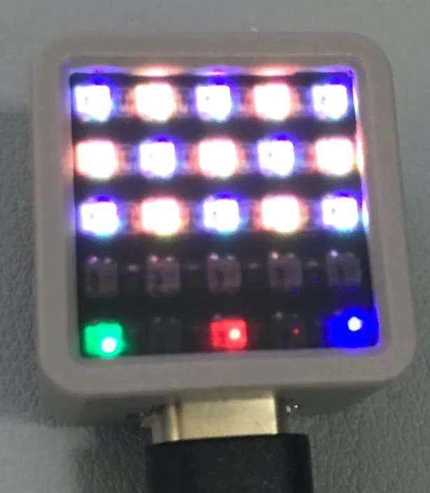
テスター仕様は、ATOM Matrix の5x5のLEDのうち、上位4行でキーボードの押した位置を点灯。
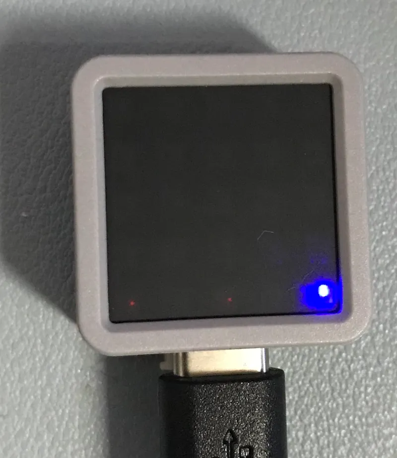
5行目の1,2カラムは、左のエンコーダ値。 5行目の3,4カラムは、右のエンコーダ値。 5行目の5カラムは、serialでデータを受け取ると、点滅する。
keyboard_checker.c · Gistc
#include "M5Atom.h"

//#define PIN_RX 22   // G0
#define PIN_RX 32   // GROVE
#define PIN_TX 26

#define PIXEL_PER_ROW 5

// Matrix Display Buffer
uint8_t DisBuff[2 + 5 * 5 * 3];

#define ORANGE              0xe07020
#define GRAY                0x686868
#define RED                 0x701212
#define BLUE                0x000070
#define GREEN               0x00ff00

uint32_t DisColormap[] = {
    // keyboard color map
    GRAY,   ORANGE, GRAY,   ORANGE, GRAY,
    ORANGE, GRAY,   ORANGE, GRAY,   ORANGE,
    GRAY,   ORANGE, GRAY,   ORANGE, GRAY,
    GRAY,   GRAY,   GRAY,   GRAY,   GRAY
};

void setup() {

    // serial console init
    Serial.begin(115200);

    // ATOM Matrix init
    M5.begin(true, false, true);
    delay(10);

    Serial1.begin(20000, SERIAL_8N1, PIN_RX, PIN_TX); // EXT_IO
    Serial.println("start");

    M5.dis.drawpix(24, GRAY);
}

uint8_t SerialBuff[128];
uint16_t SeirialBuffSize = 0;

void draw_matrix() {

    // keycode
    //     1    2    3    4    5 : 1byte(1-5)
    //     6    7    8    9   10 : 1byes(6-8) 2bytes(1-2)
    //    11   12   13   14   15 : 2byte(3-7)
    //         17        19   20 : 3byte(1, 3-4)
    // encoder
    // LEFT  ENCODE VALUE(0-127) : 5byte(1-8)
    // RIGHT ENCODE VALUE(0-127) : 6byte(1-8)

    DisBuff[0] = 0x05;
    DisBuff[1] = 0x05;

    // keyboard matrix
    for (int row = 0; row < 4; row++) {
        uint8_t val = SerialBuff[row];
        for (int col = 0; col < PIXEL_PER_ROW; col++) {
            uint32_t color = 0;

            uint32_t pixel = row*PIXEL_PER_ROW + col;
            uint32_t buf_offset = pixel * 3;

            if (val & 1<<col) {
                color = DisColormap[pixel];
            }

            uint8_t red = (color &0xff0000)>>16;
              uint8_t green = (color &0xff00)>>8;
            uint8_t blue = (color &0xff);

            DisBuff[2 + buf_offset + 0] = red;
            DisBuff[2 + buf_offset + 1] = green;
            DisBuff[2 + buf_offset + 2] = blue;

            // M5.dis.drawpix(row*5+col, 0x707070);
        }
    }

    // encoder
    for (uint8_t encoder_hand = 0; encoder_hand < 2; encoder_hand++) {

        uint8_t pixel_row = 4;
        uint8_t data_offset = 4/*enconder byte*/ + encoder_hand;
        uint8_t encoder_val = SerialBuff[data_offset];

        uint8_t color[2];
        color[0] = ((encoder_val & 0x0f)<<1) | 0x01;         // val < 128
        color[1] = (((encoder_val & 0xf0)>>4)<<1) | 0x01;    // val >= 128

        for (uint8_t col = 0; col < 2; col++) {

            uint32_t pixel = pixel_row*PIXEL_PER_ROW + encoder_hand * 2 + col;
            uint32_t buf_offset = pixel * 3;

            uint8_t red = 0;
            uint8_t green = 0;
            uint8_t blue = 0;

            if (encoder_hand == 0) {
                // left hand
                green = color[col]<<3;
            } else {
                // right hand
                red = color[col]<<3;
            }

            DisBuff[2 + buf_offset + 0] = red;
            DisBuff[2 + buf_offset + 1] = green;
            DisBuff[2 + buf_offset + 2] = blue;

            // DisBuff[2 + buf_offset + 0] = 0x70;
        }
    }

    M5.dis.displaybuff(DisBuff);
}

void loop() {

  if (Serial1.available()) {
      int inByte = Serial1.read();
      M5.dis.drawpix(24, 0x000070);
      if (inByte == 0xff) {
          // stop data
          for (int i =0; i < SeirialBuffSize; i++) {
              Serial.printf("%02x", SerialBuff[i]);
          }
          Serial.println("");
          draw_matrix();
          SeirialBuffSize = 0;

      } else {

          // matrics data
          SerialBuff[SeirialBuffSize] = inByte;
          if (SeirialBuffSize++ >= sizeof(SerialBuff)) {
              Serial.println("error");
              SeirialBuffSize = 0;
          }
    }

  } else {
      delay(50);
  }

  M5.update();
}
全部のキーを押すとこんな表示になる。